An IoT application using IoT framework? Here it is
According to the market researchers at IDC, there were 9.1 billions Internet of Things (IoT) devices installed at the end of 2013. They expect that number will increase stably and will reach 28.1 billions in 2020. In front of this huge number of connected devices, there is an enormous potential market of thousand services and application products, which will innovate rapidly at the same time just like the explosion of Android or iOS applications.
How could the relevant company adapt to this market environment? More accurately, how could the developers in this kind of company create a quality application more efficiently? The answer may be using a powerful framework to simplify the development and reduce the development time.
In this article, we will give a brief introduction about Standard OneM2M and its implementation OM2M. In order to give a more concrete global view of OneM2M as well as OM2M, we realized a PoC dedicated to a connected vehicle user case, in which we implemented two classic services (GPS tracking, real-time speed display and remote control).
OneM2M, a worldwide standard for IoT platforms and systems
OneM2M is a standard that provides a common M2M service layer that can be embedded within various hardware and software to connect IoT devices^<sup><a title="" href="#_ftn5">[1]</a>^</sup>. It was established by a consortium of ICT standards development bodies in July 2012 and the consortium includes ETSI (European Telecommunications Standards Institute), TIA (Telecommunications Industry Association Japan), TTA (Telecommunications Technology Association Korea), TTC (Telecommunication Technology Committee USA) and CCSA (China Communications Standards Association).
The layered model of oneM2M comprises 3 layers: Application Layer, Common Services Layer and the underlying Network Services Layer. Just like the graph below depicts, this model supports end-to-end (E2E) M2M Service^<sup><a title="" href="#_ftn5">[1]</a>^</sup>.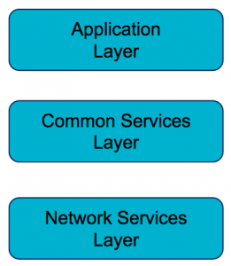
This clause describes the services provided by the Common Services Layer in the M2M System. Such services reside within a CSE and are referred to as Common Services Functions (CSFs). An instantiation of a CSE in a Node comprises a subset of the CSFs^<sup><a title="" href="#_ftn5">[1]</a>^</sup>. Those CSFs are listed in the graph above. Mca, Mcc, Mcn are the reference points, which provide the communication between two different entities. The CSFs contained inside the CSE can interact with each other.
The graph below depicts all the possibilities to construct a system and the reference points listed below.
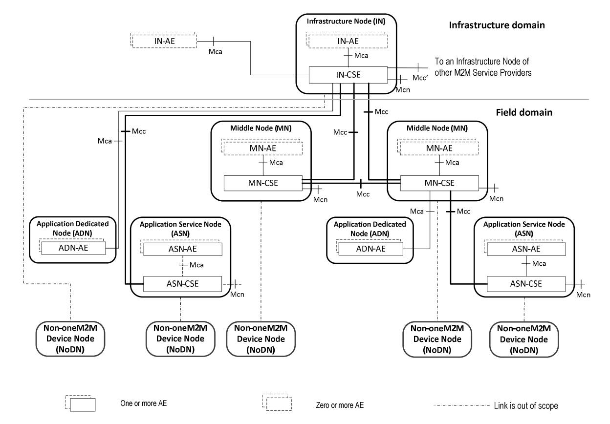
- Mca: the interface point between AE and CSE which provides the applications access to the common services.
- Mcc: the reference point between two CSEs.
- Mcn: the reference point between CSE and underlying NSE like transport and connectivity services.
- Mcc’: the interface between two M2M service providers.
- IN: Infrastructure Node
- NoDN: Non-oneM2M Device Node
OM2M - The implementation of OneM2M
OM2M project is an open source implementation of OneM2M and SmartM2M standard that initiated by LAAS-CNRS. It provides a horizontal M2M service platform for developing services independently of the underlying network, with the aim of facilitating the deployment of vertical applications and heterogeneous devices^<sup><a title="" href="#_ftn5">[2]</a>^</sup>.
OM2M provides a horizontal Service Common Entity (CSE). Those CSEs can be deployed in an M2M server, a gateway, or a device. The services provided by CSE like Application Enablement, Security, Triggering, Notification, Persistency, Device Interworking, Device Management, etc. can be used by developers to simplify the application development.
Proof of Concept using the OM2M solution
With the purpose of testing OM2M and to gain the retro-experience of this PoC, I, as an intern at OCTO Technology have the chance to realize this PoC dedicated to the user case of connected vehicle.
Use case description and Macro functions of the implemented system
The Internet of Things is breaking fresh ground for car manufacturers by introducing entirely new layers to the traditional concept of a car. This upgrade — the connected, smart car — comes as a revolutionary way for us to drive and stay in touch with the world around at the same time.
On the inspiration of this new concept of the car, we decided to try to apply the IoT framework to the system of a connected vehicle with the most classic service asked by the driver and provided by the manufacturer in various ways — GPS function and real-time speed display function.
Besides the GPS function, a remote control function was anticipated to test the bi-directional of the dataflow.
1, Localization:
The application on the smartphone can display where your device is on the map and the speed of your device.
2, Remote control:
The application on the smartphone can remotely control your device. Here, we are using the application to start and stop a part of the program on the device.
Architecture of the prototyped system
An architecture dedicated to the realization of this use case is described in the diagram below:

Three parts are found in this architecture: the side of vehicle, the cloud and the user terminal. The detail information listed in the next paragraph:
- Module GPS: Pixnor Waveshare UART GPS NEO – 7M(B). This device will receive the GPS, speed signals and generates the GPS, speed data in the form of norm NMEA.
- Raspberry pi: Raspberry Pi 3 supports WiFi and BT/BLE. It will work as a gateway and manager the data of GPS and speed.
- PC: MacBook Pro OS X El Capitan 10.11.4. In the prototype, we replace the cloud service with personal computer for the reason of simplification. Here, the PC will work as a server.
- Mobile phone: An Android cellphone with the version 6 on which, there is an Android application running as a terminal to the user.
- WiFi LAN: OCTO WiFi network.
But, how does the actual architecture represent the operational architecture OneM2M mentioned in the previous paragraph? The diagram below gives the answer.
The GPS module will take the place of Non-oneM2M Device Node with the reason that lack of “intelligence”, we cannot install the required package library to run the whole OM2M on the device. The solution is to add a Middle Node (Gateway), which will provide the connection service and control the GPS device. The cloud service, replaced by a PC in the prototype architecture, runs as a server acting like an orchestrator and takes the role of infrastructure Node in the whole architecture. Because no Android version of OM2M exists, the user terminal was realized in the prototype architecture is represented in the operational architecture OneM2M like an IN-AE (Infrastructure Node - Application Entity).
The technical implementation of our prototype using OM2M
OM2M requires JAVA 1.7 and Apache Maven 3. The integrated development environment shows in the below diagram.
The entities organization of the system below gives us a panorama that how we integrate our proper program in an OM2M environment.
A GPS control program is written on the MN side to communicate with the GPS device, at the same time, two programs (initialization and running) are integrated in the MN as Plugin on OSGi framework that will collaborate with other OM2M OSGi plugins to realize the purpose functions.
Here is the detailed entities structure of the system. 
- Request Sender: The request sender is a utility class that will create oneM2M requests to send to the CSE using Java objects.
- ObixUtil: The ObixUtil is here to create oBIX representation for the devices. Convert the description and the measured data of the device to oBIX XML representation.
- Activator: It is the entry point of OSGi plugins. The Activator class contains the implementation of the state() and stop() methods used to activate and deactivate the plugins.
- Controller: Used to make the interaction between the devices following the orders coming from the oneM2M interface. As your plugin receives requests, the controller performs the corresponding operation on the devices.
- Connector: It communicates with the GPS module by UART and pass the data to the parser.
- Parser: GPS NMEA data format processing, to get the final useful data format.
- Router: Router class implements the InterworkingService interface and will be the entry point for requests that target your plugins. It will send the request to the corresponding method of the controller.
- Request redirector: Redirect the receiving message upon the inscriptions and subscriptions.
- Database: This class implements the persistence services and deals with DB operations.
- Event notifier: Transfers the notification messages.
- REST client: Used to create the necessary component in the system as a REST client.
- Web Listener: A socket based listener to receive the notifications.
- Displayer: A part of the program to communicate with the user by using a google API.
How the system works?
The system works based on a subscription and notification system. The subscribers subscribe to the data that they need and the notifications will be sent to the subscribers when there is a modification of the data.
In our PoC, the gateway was recognised by the cloud after the configuration (exchange of the IP addresses and accessed port). In other words, MN-CSE connected with the IN-CSE. Step 1, The creation of the entities in the system: the device and android application entities like MN-AE MY_GPS, MN-AECONTROLLER, IN-AEGPS, IN-AE MY_CONTROLLER are created by launching the initiation plugin program. Step 2, The creation of subscription: it’s the key point of the system, the subscription allows to distribute the data to the right destination and this distribution is achieved in the form of sending notification messages. In the localization use case, the subscription of IN-AEGPS to the data of MN-AE MY_GPS is created. In the remote control use case, the subscription of MN-AECONTROLLER to the data of IN-AE MY_CONTROLLER is created. Step 3, Notification messages sending: after the successful creation of a subscription, the notification will be sent when the data is modified. In the use case of localization, when there is a creation or modification of data, for example, a new GPS coordinate data was created, the notification will be sent to IN-AEGPS and then, the android application can parse the coordinates in the notification message and display it on the map. For speed data, the processes are the same, GPS coordinate data was replaced by speed data. In the use case of remote control, when the button is clicked, a new control data is generated, the notification will be sent to MN-AECONTROLLER and then, the related program will be executed, for example, to stop creating GPS coordinate data instances.
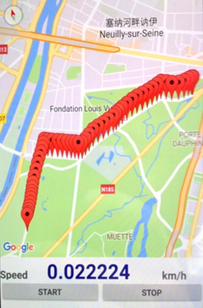
A test of this prototype has been launched by the head of the IoT tribe and myself. The test environment was chosen as a real car, outdoors with a 4G connection. The system was installed temporarily in the car and powered by the battery of the vehicle.
Result: Prototype system ran correctly in the car and showed a correct traces tracked by the system and speed displayed correctly in the application like on the photo taken during the test.
[playlist type="video" ids="65325"]
Conclusion
OM2M, the implementation of OneM2M worked well in this use case, thanks to the subscription and notification services provided by the framework. Data flows were transmitted fluently between the Android application, gateway and server sides. The prototype system is constructed on a simplified network. A real world network is more constrained on security and network management. But this PoC gives us an expect of the possibility to develop a real system by using this framework. We also stand to wait the maturity of the OM2M implementation and the welling to test other OneM2M based implementations. An inspiration news came out a few days ago that standard OneM2M published its second release in which will enable the interworking between systems using AllSeen Alliance’s AllJoyn, Open Connectivity Foundation’s OIC, and the Open Mobile Alliance’s Lightweight M2M (LWM2M).
OneM2M release 2 specifications TS 0001 2.10.0 Functional Architecture